Laser Cut Cardboard Creation: Phone Tripod
In week three of my physical prototyping class, I learned to use a ULS laser cutter and use Adobe Illustrator. I was taken with creating a cell phone stand for shooting video of an object below it (such as a paper prototype or mobile app). This included the following design requirements:
must be cut from not more than two sheets of 18 x 24" flute and/or two sheets of chipboard (we will provide these to you). If you wish, you may combine these materials in your design.
must not use any glue, tape, or other fastening materials to assemble and use
must be able to be dissembled into pieces that can be stored flat and transported (as in a backpack)
No downloaded designs.
Design
I started my process by creating two goals that focused on usability and desirability. I referred to these goals throughout my prototyping process.
Usability: A user can attach and detach a phone to the prototype and record video using the phone to capture the entire size of the prototype.
Desirability: The shape and form of the prototype is inviting to the user, and the resulting video shot using the prototype is clear and interesting. All pieces of the prototype are small enough to fit in a shoe box for easy storage.
I made my design decisions by working through an iteration process where I tested each prototype, took notes, then improved and changed my design. This began with initial research, where I started out by sketching out some initial ideas that I had and then began to search the internet for existing ideas and solutions to a phone tripod for filming.
After a number of sketches, I cut my first paper prototype from printer paper with the goal of seeing of my 2D sketch could take 3D shape. This was successful, but was a much smaller scale, so I moved on to a second paper prototype that was cut with an exacto knife out of construction paper. The goal of this was to determine the measurements for the prototype and to see if it could stand on its own. The prototype did not stand on its own, so I added supports to each leg using a slot method. This helped the prototype stand, but the paper was still too thin to support the weight of a phone.
I then made my first laser cut prototype from chipboard, however, the material was too flexible and the design had too many fragile parts, so I went back to sketching. This is where I scoped down my prototype, removing the ability to change camera angles. I made a new paper prototype of the top of the tripod. Then I cut out the entire prototype from scrap cardboard from an amazon box. This held my phone. Then I made my final laser cut prototype out of cardboard. I had to iterate individual pieces to determine the thickness of the cardboard and kerf.
Sketches
My sketches included initial ideas, sketches of individual parts of the prototype, and sketches of different iterations of my prototype.

Initial sketches, sketches after researching existing tripods, and sketches of initial design before creating paper prototype.

Side view and top view before making chipboard prototype, sketches of ideas for leg support, and side view of cardboard prototype.
Prototype
My prototyping process began with a lesson in laser printing, where I printed a bookmark and learned about vectors and rastoring. To visualize my sketches and see if they could become a 3D object, I make my first paper prototype. This was a prototype that focused only on the top of the tripod that holds the phone.

Laser cut lesson bookmark, and paper prototype of the top of the tripod.
Next, I made a paper prototype out of card stock to determine the correct measurements of the prototype. This was successful, but did not stand on its own and was not strong enough to hold the phone. My next iteration was made of chipboard, the goal of this prototype was to learn Adobe Illustrator and to made a .svg file and to laser print the prototype at full scale.

Second paper prototype and laser cutting the chip board prototype.

Chipboard prototype
After the chip board prototype, I went back to my sketchbook and began sketching ways to make the top of the prototype more sturdy to support the phone’s weight. I came up with the following critique of my own design:
Things to change after making the first chip board prototype:
Make the slot supports go all the way up the legs and all three legs
This was addressed by using cardboard which was more sturdy
Change the support system for the phone, make it more centered so that weight is distributed.
This was addressed by changing the design of the top of the tripod.
Make the part that holds the phone support the phone more so that it does not fall out
This was addressed by scoping down the prototype to remove the ability to change angles, and using cardboard material.
I used an Exacto knife to cut out the new design with scrap cardboard.

Hand-cut cardboard prototype: hold phone. Adobe Illustrator design showing measurements.
Next, I tested the kerf of the laser cutter by cutting a small piece of my final prototype multiple times with the laser cutter and adjusting the width of the slots each time. I settled on using a 0.135inch width for all of the slots to account for the kerf and the thickness of the final cardboard that I used.

Laser cutting the cardboard, and first iterations to determine thickness of cardboard.
I laser printed all of the final pieces after adjusting the Adobe Illustrator file to reflect the changes to the top of the tripod and the thickness of the cardboard.

Final prototype without phone.

Final prototype with phone

Adobe Illustrator file for laser cutting

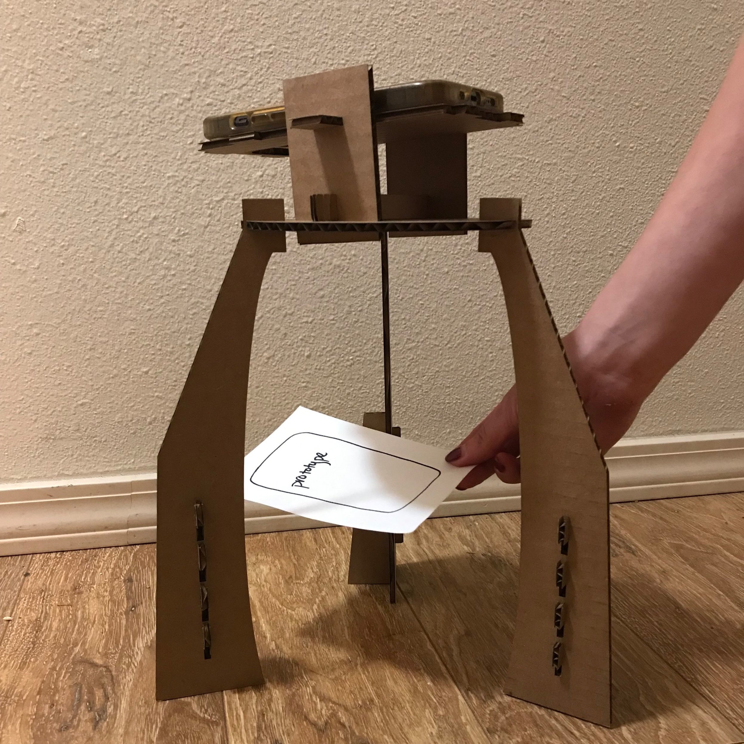
Filming an object with the final prototype
Analysis
I tested my prototype with one HCDE professor, three design students, and one student outside of HCDE. This consisted of two five-minute testing sessions, for a total of 10 minutes of testing. Based on this, I gathered the following insights:
Things That Worked Well:
The fit of the cardboard slots is very snug and secure
Participants liked the form of the rounded legs and circular base
One participant pointed out that the shape of the piece that supports the phone is in the shape of a phone, indicating where the phone should be placed.
Participants mentioned that it seems very feasible and usable, and enjoyed the “futuristic” look of it.
Things That Could Be Improved:
One participant recommended that I test the design with different phone models to broaden the scope and allow a wider range of users. The specifications and intention were meant for my phone, but could be broadened in future iterations.
One participant noted that the legs might wobble a bit if bumped while filming and suggested that supports be added to either side of the legs. They also suggested that the legs could be made thicker with two pieces of cardboard together.
In conclusion, my prototyping process was successful to learn what techniques and form would be useful for my design. The form and function of my phone tripod met the design requirements and determined that this product would be desirable for a user. If I had more time for this project, I would complete another iteration to focus on provided more support to the base and legs of the design, removing any chance of movement while filming. This could be achieved by adding supports to the other side of each leg and making the cross supports go all the way up the legs to ensure longevity. If I had more time, I would also expand the impact of my design by catering towards different phone models. Overall, my final tripod prototype met my goals of prototyping for feasibility and I received positive feedback during my critique, therefore I will not be completing another iteration of my tripod for this assignment.